We needed an "electro quiz" for the schallaburg exhibition "60ies".
But instead of using an simple contact system lightning a green bulb if the question is correct, we decided to make it a bit more complicated.
we wanted a sound/ green bulb combination for the correct answers and a red bulb for any wrong answer including action if shortening the contact pins.
additionally we wanted, except for the layout, two identically gaming systems.
Our choice was arduino and a simple resistor matrix.
the gaming panel:
1 we connected every correct answer pair with 10 ohms resistors.
2 every pair was connected with 47 ohms in series to another pair.
the arduino side:
using analogread(), we checked the resistor value between the 2 contact pins.
1 correct means a very but not zero value.
2 a nearly to zero value means no interaction
3 a higher than zero value means wrong answer
4 a nearly maximum value means short
any interaction triggers a digitalout pin high, which switches a bulb via a transistor.
a correct interaction starts a generated sound additionally
we adopted a sound generation script from
www.beavisaudio.com/Projects/digital/ArduinoPunkConsole/
a serial display helped to measure out the correct values.
the script:
#define DigitalOutSignalA 9
#define DigitalOutSignalB 10
//http://ctheds.wordpress.com/2007/10/30/tip-120/
// NPN TRANSISTOR
//// widerständer so um die 10 ohm und für die großen umd die 50 ohm
int steps[] = {100,120,150}; //kurzer
int duration = 500;
int pitchval = 4;
int led = 13;
int sensorPinA = 0; // select the input pin for the potentiometer
int sensorPinB = 1; // select the input pin for the potentiometer
int ledPinA = 7; // select the pin for the LED
int ledPinB = 12; // select the pin for the LED
int errorPinA = 8; // select the pin for the LED
int errorPinB = 11; // select the pin for the LED
int sensorValueA = 0; // variable to store the value coming from the sensor
int sensorValueB = 0; // variable to store the value coming from the sensor
unsigned long trigtik;
unsigned long trigoka;
unsigned long trigokb;
int flag = 1;
int okflaga = 0;
int okflagb = 0;
void setup() {
// declare the ledPin as an OUTPUT:
pinMode(ledPinA, OUTPUT);
pinMode(ledPinB, OUTPUT);
pinMode(errorPinA, OUTPUT);
pinMode(errorPinB, OUTPUT);
pinMode(led, OUTPUT);
Serial.begin(9600);
}
void loop() {
if (millis() < 100){
trigtik = 0;
}
//ledblinken
if ((millis() > trigtik)){
trigtik = millis() + 1000;
if (flag  1){ 1){
digitalWrite(led, LOW);
flag = 2; //lauten
}
else{
digitalWrite(led, HIGH);
flag = 1; //lauten
}
}
////
sensorValueB = 0;
sensorValueA = 0;
// digitalWrite(led, LOW);
///AAAAA
sensorValueA = analogRead(sensorPinA); // read the value from the sensor:
Serial.print(sensorValueA, DEC); //command flag
Serial.print("-");
if (sensorValueA >= 0 && sensorValueA <= 10){
digitalWrite(ledPinA, LOW);
digitalWrite(errorPinA, LOW);
okflaga = 0;
}
else if (sensorValueA > 10 && sensorValueA <= 600){ //error
if (millis() > trigoka){
digitalWrite(errorPinA, HIGH);
digitalWrite(ledPinA, LOW);
okflaga = 0;
}
}
else if (sensorValueA <= 900 && sensorValueA > 600){ //ok
digitalWrite(ledPinA, HIGH);
digitalWrite(errorPinA, LOW);
trigoka = millis() + 1000;
if (okflaga < 1){
okflaga;
for (int i=0; i<3; i) {
freqoutA (steps[i], duration);
delay(10);
}
}
}
else if (sensorValueA > 900){ //kurzer
digitalWrite(errorPinA, HIGH);
digitalWrite(ledPinA, LOW);
okflaga = 0;
}
sensorValueB = analogRead(sensorPinB); // read the value from the sensor:
Serial.print(sensorValueB, DEC); //command flag
Serial.println(",");
if (sensorValueB >= 0 && sensorValueB <= 10){ //// widerständer so um die 10 ohm und für die großen umd die 50 ohm
digitalWrite(ledPinB, LOW);
digitalWrite(errorPinB, LOW);
okflagb = 0;
}
else if (sensorValueB > 10 && sensorValueB <= 600){ //error#
if (millis() > trigokb){
digitalWrite(errorPinB, HIGH);
digitalWrite(ledPinB, LOW);
okflagb = 0;
}
}
else if (sensorValueB <= 900 && sensorValueB > 600){ //ok
digitalWrite(ledPinB, HIGH);
digitalWrite(errorPinB, LOW);
trigokb = millis() + 1000;
if (okflagb < 1){
okflagb;
for (int i=0; i<3; i) {
freqoutB (steps[i], duration);
delay(10);
}
}
}
else if (sensorValueB > 900){ //kurzer
digitalWrite(errorPinB, HIGH);
digitalWrite(ledPinB, LOW);
okflagb = 0;
}
}
void freqoutA(int freq, int t)
{
int hperiod; //calculate 1/2 period in us
long cycles, i;
// subtract 7 us to make up for digitalWrite overhead - determined empirically
hperiod = (500000 / ((freq - 7) * pitchval));
// calculate cycles
cycles = ((long)freq * (long)t) / 1000; // calculate cycles
for (i=0; i<= cycles; i)
{ // play note for t ms
digitalWrite(DigitalOutSignalA, HIGH);
delayMicroseconds(hperiod);
digitalWrite(DigitalOutSignalA, LOW);
delayMicroseconds(hperiod - 1); // - 1 to make up for fractional microsecond in digitaWrite overhead
}
}
void freqoutB(int freq, int t)
{
int hperiod; //calculate 1/2 period in us
long cycles, i;
// subtract 7 us to make up for digitalWrite overhead - determined empirically
hperiod = (500000 / ((freq - 7) * pitchval));
// calculate cycles
cycles = ((long)freq * (long)t) / 1000; // calculate cycles
for (i=0; i<= cycles; i)
{ // play note for t ms
digitalWrite(DigitalOutSignalB, HIGH);
delayMicroseconds(hperiod);
digitalWrite(DigitalOutSignalB, LOW);
delayMicroseconds(hperiod - 1); // - 1 to make up for fractional microsecond in digitaWrite overhead
}
}
/////end script
ein elektroquiz - finde die zusammengehörigen bilder!
sehr einfach wenn man nur eine grüne lampe für den richtigen kontakt braucht.
aber was ist wenn auch bei einem falschen kontakt eine lampe leuchten soll? - rot z.B.
nach einer nachdenknacht kam ich auf die idee, arduino einzusetzen:
2 korrekte kontakte sind mit 10 ohm miteinander verdrahtet (bild 2)
jedes korrekte kontaktpaar ist mit je einem falschen in serie mit 47 ohm verdrahtet. (bild 2)
somit ergibt sich durch eine simple widerstandsmatrix das spiel.
mit arduino
sensorValueA = analogRead(sensorPinA); //zwischen 0 und 1024
frage ich den widerstand ab.
ist er klein ist die frage korrekt
ist er nicht da sind keine kontakte geschlossen
ist er größer als klein ist die frage falsch
ist er riesig sind die kontaktstifte verbunden
über einen t120 transistor schalte ich die entsprechende lampe ein bzw. aus.
in meinem fall gibt es für den richtigen kontakt noch einen belohnungston (recycled von arduino punk)
www.gestern.com/index3.php?act=showmain&V_PRIMARY=24&ka=19&su=24
über den pwm ausgang des arduino (2 mono verstärker rechts bei bild 3), eine serielle kontrollanzeige für die widerstandswerte zur programmierung und weil ich 2 spiele parallel habe, habe ich die transistoren und den code doppelt.
hoffe es hält die kinderdauerbelastung auf der schallaburg aus.
|
|

panel and contacts
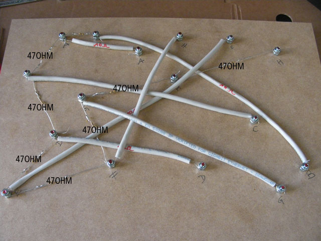
contact wiring
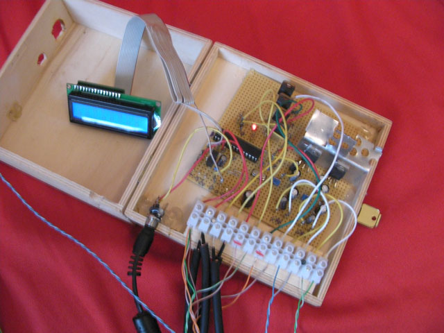
the electronic, see the atmega and transistors left, the two audio amps with heatsinks right
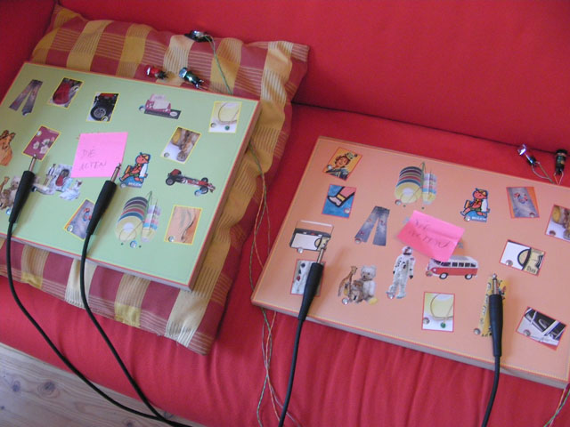
2 games 1 electronic
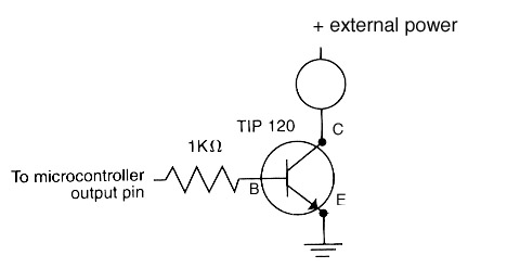
http://ctheds.wordpress.com/2007/10/30/tip-120/
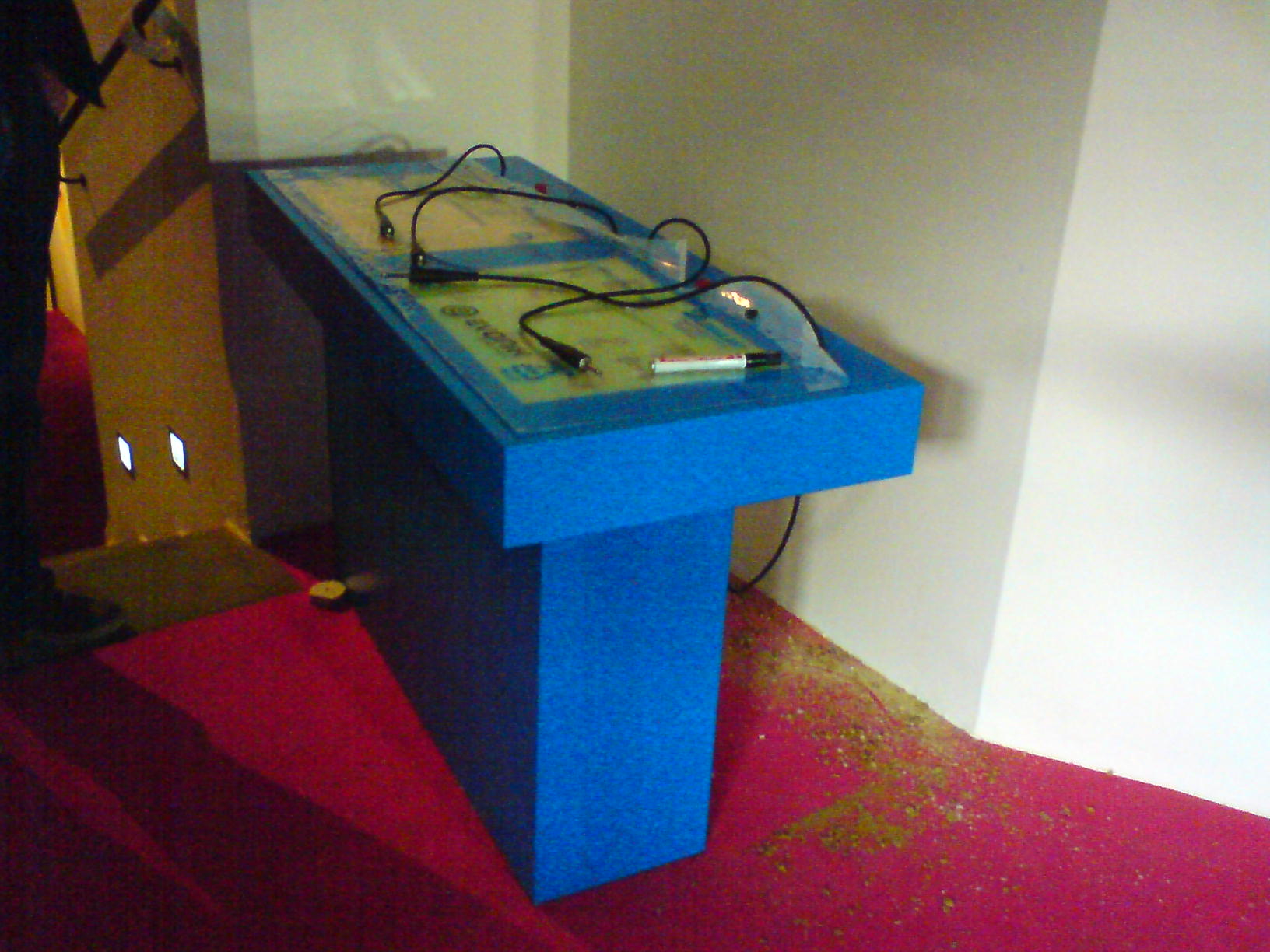
the finished console
|
)
)
)
)
)